Dusty's Magic Rizz Ball
Project Overview
This project uses a Raspberry Pi Pico, a tilt sensor, LEDs, and a buzzer to create an interactive Magic 8 Ball experience. Tilt the device to get an answer, accompanied by LED lights and sounds.

Live demonstration of the Magic Rizz Ball hardware setup showing the tilt sensor, LEDs, and interactive response system in action.
Hardware Setup
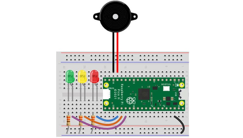
- Tilt Sensor connected to GP26
- Red LED to GP18
- Amber LED to GP19
- Green LED to GP20
- Buzzer connected to GP13
MicroPython Code
# Imports
from machine import Pin, PWM
import time
import random

# Define pin for the tilt sensor
tilt_sensor = Pin(26, Pin.IN, Pin.PULL_DOWN)  # Gives HIGH when tilted

# Set up the LED pins
red = Pin(18, Pin.OUT)
amber = Pin(19, Pin.OUT)
green = Pin(20, Pin.OUT)

# Set up the Buzzer pin as PWM
buzzer = PWM(Pin(13))

# Notes for different answer types
C = 523
D = 587
E = 659
F = 698
G = 784

# Magic 8 Ball responses with LED and melody association
responses = [
    ("It is certain.", green, [C, D, E, G]),
    ("It is decidedly so.", green, [C, D, E, G]),
    ("Without a doubt!", green, [C, D, E, G]),
    ("Yes, definitely!", green, [C, D, E, G]),
    ("You may rely on it.", green, [C, D, E, G]),
    ("As I see it, yes.", green, [C, D, E, G]),
    ("Most likely...", green, [C, D, E, G]),
    ("Outlook GOOD!", green, [C, D, E, G]),
    ("Yes.", green, [C, D, E, G]),
    ("Signs point to... yes!", green, [C, D, E, G]),
    ("Umm... let's try this again", amber, [C, E, G, E, C]),
    ("Ask again later...", amber, [C, E, G, E, C]),
    ("It's better to not tell you now...", amber, [C, E, G, E, C]),
    ("The Universe says Yes.", green, [C, D, E, G]),
    ("Concentrate and ask again.", amber, [C, E, G, E, C]),
    ("Don't count on it.", red, [G, E, D, C]),
    ("My reply is no.", red, [G, E, D, C]),
    ("The Universe says no.", red, [G, E, D, C]),
    ("Outlook not so good.", red, [G, E, D, C]),
    ("Doubt it.", red, [G, E, D, C]),
    ("How f🤬king dumb are you?", red, [G, E, D, C]),
    ("You M U S T be delulu for asking.", red, [G, E, D, C]),
    ("You REALLY shouldn't.", red, [G, E, D, C])
]

# Function to play a note
def play_note(note, duration):
    buzzer.duty_u16(32768)  # Medium volume
    buzzer.freq(note)
    time.sleep(duration)
    buzzer.duty_u16(0)

# Function to simulate debounce for the tilt sensor
def debounce(pin, delay=0.05):
    initial = pin.value()
    time.sleep(delay)
    return pin.value() == initial

# LED animation for generating answer
def generate_animation():
    for i in range(3):  # Three cycles of animation
        for led in [red, amber, green]:
            led.on()
            time.sleep(0.1)
            led.off()

# Main loop
print("Magic 8 Ball ready. Tilt to ask a question.")
previous_state = tilt_sensor.value()  # Assume initial state

while True:
    current_state = tilt_sensor.value()

    if current_state == 1 and previous_state == 0 and debounce(tilt_sensor):
        generate_animation()  # LED animation while generating answer
        answer, led, melody = random.choice(responses)
        print(f"\nMagic 8 Ball says: {answer}")
        led.on()  # Light up the corresponding LED
        for note in melody:
            play_note(note, 0.2)  # Play the melody for the answer type
        time.sleep(1)  # Show the LED for 1 second after the melody
        led.off()

    previous_state = current_state
    time.sleep(0.1)  # Small delay to prevent too frequent readings
Notes
- Ensure your Pico is flashed with the latest MicroPython firmware.
- The new responses include some humor and sarcasm. Adjust or censor as needed for your audience.
- The melodies are simple and can be expanded or changed to suit the answers or for variety.
Step-by-Step Guide to Creating an Enhanced Magic 8 Ball
Materials Needed:
- Raspberry Pi Pico
- Tilt Sensor (like SW-520D)
- 3 LEDs (Red, Amber, Yellow)
- Buzzer (passive or active)
- Breadboard
- Jumper Wires
- USB Cable for programming
- Resistors (220Ω for LEDs, 1kΩ for buzzer if passive)
Step 1: Hardware Setup

Complete wiring diagram showing the Raspberry Pi Pico, LED array, and buzzer setup

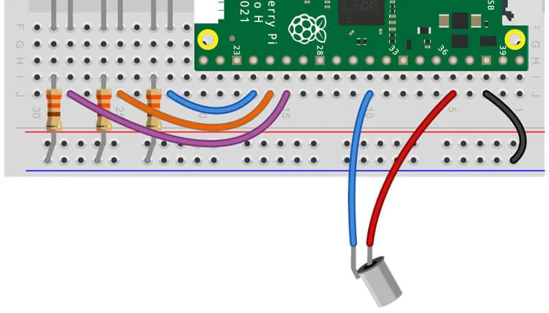
Detailed view of the LED connections with resistors and color-coded wiring
- Connect the Tilt Sensor:
- VCC to 3V3 on Pico
- GND to GND on Pico
- Signal to GP26 on Pico
- Connect the LEDs:
- Red LED:
- Anode to GP18
- Cathode through a 220Ω resistor to GND
- Amber LED:
- Anode to GP19
- Cathode through a 220Ω resistor to GND
- Green LED:
- Anode to GP20
- Cathode through a 220Ω resistor to GND
- Red LED:
- Connect the Buzzer:
- If using a passive buzzer:
- Pin to GP13
- GND through a 1kΩ resistor to GND
- If using an active buzzer:
- Positive to GP13
- Negative to GND
- If using a passive buzzer:
Step 2: Software Setup
- Install Thonny IDE for MicroPython development.
- Flash MicroPython on Raspberry Pi Pico:
- Connect Pico, enter USB mass storage mode by holding BOOTSEL while plugging in, then drag and drop the MicroPython UF2 file.
- Open Thonny and connect to your Pico.
Step 3: Code Implementation
Copy and paste the MicroPython code provided above into your Thonny IDE.
Step 4: Upload and Test
- Click "Run current script" or press F5 in Thonny to upload and run the script.
Pro Tips and Suggestions:
- Custom Melodies: Add or change the melodies to match the answer types, or include user-defined melodies.
- Interactive Elements: Consider adding buttons to manually trigger responses or change settings.
- Battery and Case: For mobility, use batteries and encase the project in a spherical container for an authentic look.
- Adjust Audio: Change notes, duration, or even implement volume control with PWM duty cycle adjustments.
- User Feedback: Add a small screen or use serial communication for more detailed feedback or interaction.
- Expand Sensors: Introduce more sensors for different interaction methods, like light sensors for LED brightness adjustment.
- Debounce Refinement: If tilt detection is too sensitive, refine debounce logic or consider hardware debounce solutions.
This project not only introduces you to basic electronics and MicroPython but also encourages creativity in building interactive gadgets. Enjoy your Magic 8 Ball!